The correct centrifugal pump is selected based on the application, model and/or type and the duty point. The duty point of the centrifugal pump is the most important part of the selection.
If a centrifugal pump is found that ideally matches the duty point you get
- maximum comfort;
- highest return;
- maximum operational reliability and service life.
The duty point is determined by:
- the required flow rate;
- the required delivery head;
- (NPSH value of installation);
- the fluid used (temperature, density, viscosity).
Flow rate
The flow rate, also called flow, is the amount of fluid that passes per unit of time.
Formula to calculate the flow rate.
At which:
- Q = flow/volume flow
- V = volume
- t = time
The flow rate is generally expressed in the unit m³/s (cubic metres per second). Within the pump industry this is usually expressed in m³/h (cubic metres per hour).
Centrifugal pump flow rate with a closed heating system
If a new circulator is to be installed in a heating system, its size is determined according to the flow rate using the following formula:
Formula for calculating the flow / volume flow
- QPU = flow rate of the pump at the design point in [m³/h]
- QN = heat demand of the surface to be heated in [kW]
- 1.163 = specific heat capacity in [Wh/kgK]
- ∆ (vartheta) = design temperature difference between heating flow and return
- [K], this can be based on 10 - 20 K for standard installations.
Delivery head
Pump head of centrifugal pump for closed heating systems
To transport the pumped fluid to any point of the heater, the pump must overcome the sum of all resistances. In case the path of the pipe system and the nominal diameters of the installed pipes are difficult to determine, this formula applies as a rough calculation of the delivery head:
Formula for calculating the head of the pump
- R = Friction loss in the straight pipe [Pa/m]. For standard installations 50 Pa / m to 150 Pa / m can be used (depending on the year of construction of the house, older houses have a smaller pressure loss due to the larger nominal diameters used. 50 Pa / m).
- L = Length of the most unfavourable heating line [m] for flow or return or: (length of the house + width of the house + height of the house) x 2
- ZF = Multiplication factor for:
-
- Bends/taps ≈ 1.3
- Thermostatic valve ≈ 1.7
- If, among other things, these built-in elements are present, a ZF of 2.2 can be used.
- Bends/taps ≈ 1.3
- Thermostatic valve ≈ 1.7
- Three-way valve ≈ 1.2
- If these built-in elements are present, a ZF of 2.6 can be used.
- 10,000 ≈ Conversion factor Pa (Pascal) to m (metre).
- The value 10,000 is used and is approximately the conversion from pascals (Pa) to metres of water column (mH²O / mWs / mWk / m). The exact conversion can be done with our online units’ conversion tool.
NPSH and cavitation
Cavitation means the implosion of the formed vapour bubbles (hollow spaces) as a result of local underpressure formation under the evaporation pressure of the fluid to be transported at the impeller inlet. This leads to a reduced capacity (delivery head), agitated running characteristics, reduced efficiency, noises and material defects (in the pump).
The expansion and implosion of small air bubbles in areas of higher pressure (e.g. near the impeller outlet) creates pressure surges that can damage the hydraulic system. The first signs of this are noises or damage at the impeller inlet.
An important value for a centrifugal pump is the NPSH value (Net Positive Suction Head). It indicates the minimum pressure at the pump inlet that this pump construction requires to operate without cavitation, i.e. the additional pressure required to prevent the fluid from evaporating and to keep it in a liquid state.
The NPSH value is influenced on the pump side by the impeller shape, pump speed and on the ambient side by fluid temperature, water cover and atmospheric pressure.
Air in centrifugal pump leads to cavitation
To prevent cavitation, the pumped fluid must be fed to the centrifugal pump with a certain inlet height. The size of this minimum inlet height depends on the temperature and pressure of the pumped fluid.
Other options for preventing cavitation:
- increase static pressure;
- lower fluid temperature (lower vapour pressure PD);
- pump with a low NPSH value (minimum inlet height)
Pump curve
The delivery head of a pump H is the mechanical energy transferred by the pump into the fluid, related to the gravity of the fluid, under the local gravity.
Short formula for calculating the head
- H = delivery head;
- E = usable mechanical energy [N • m];
- G = weight load [N].
The pressure increase generated in the pump and the flow rate of the pump is dependent on each other. This dependence is shown in a diagram as a pump characteristic curve.
The vertical axis, the ordinate, indicates the delivery head H of the pump in metres [m]. Other scales are possible. The following global conversion values apply:
10 m ≈ 1 bar = 100,000 Pa = 100 kPa
The horizontal axis, the abscissa, shows the division for the flow rate Q of the pump in cubic metres per hour [m³/h]. A different axis scale, for example (l/s), is possible.
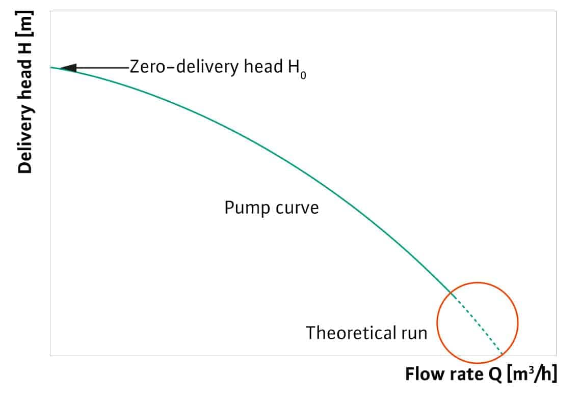
Pump characteristic explained
The characteristic curve shows the following relationships: The electric drive energy is converted (taking into account the overall efficiency) in the pump into the hydraulic energy forms of pressure increase and movement. If the pump runs against a closed valve, the maximum pump pressure is created. This is referred to as the zero-delivery head H0 of the pump. When the valve is opened slowly, the pumped fluid starts to flow. This converts part of the propulsion energy into kinetic energy. The original pressure can then no longer be maintained. The characteristic curve has a decreasing course. Theoretically, the intersection of the characteristic curve with the flow axis is reached when the water only has kinetic energy and no more pressure is built up. However, since a piping system always has an internal resistance, the actual characteristic curves end before reaching the flow axis.
Depending on the steepness and the duty point change, different flow and pressure changes arise.
- flat-running characteristic curve;
-
- larger flow change, but small pressure change;
- steeply graduated characteristic curve;
-
- smaller flow change, but large pressure change.
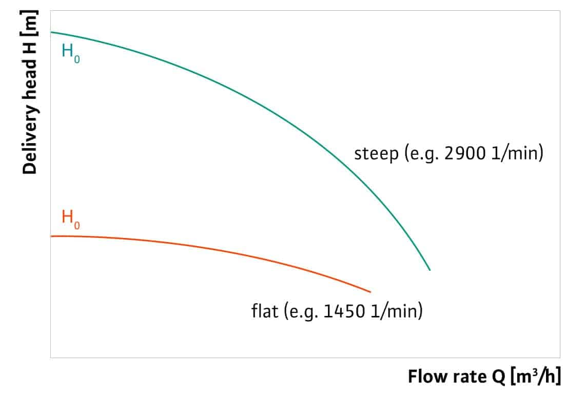
Different steepness, for example depending on the motor speed with the same pump housing and the same impeller
System curve
The internal frictional resistance in the pipe leads to a pressure loss of the pumped fluid corresponding to the entire length. This pressure loss also depends on the temperature of the flowing fluid, its viscosity, the flow velocity, the fittings, the aggregates and the frictional resistance in the pipe, consisting of pipe diameter, pipe roughness and pipe length. This is shown in a system curve . The same diagram as for the characteristic curve is used for this.
Pump characteristic explained
The course of the system curve shows the following relationships:
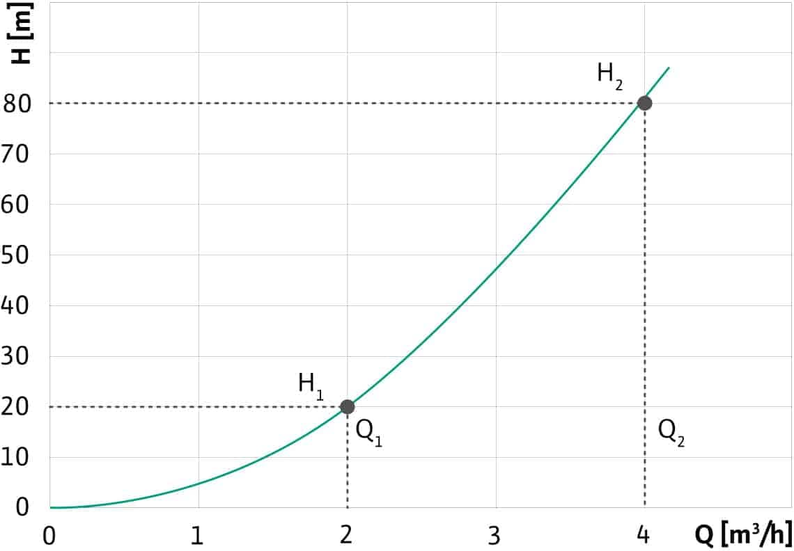
The cause of the frictional resistance in the pipe is the friction of the water along the walls, the friction of the water droplets against each other and the changes in the shape of the pipe. When the flow rate changes, for example by opening and closing the thermostat valves, the speed of the water also changes and thus the frictional resistance of the pipe. Since the unchanged pipe diameter is to be considered as a flow-through plane, the resistance changes quadratically. Graphically, this therefore results in the shape of a parabola.
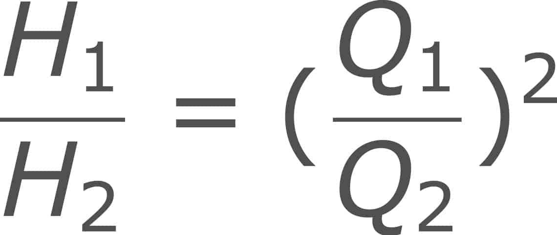
Formula for calculating changing resistance
If the flow rate in the pipe system is halved, the delivery head drops to a quarter. If the flow rate is doubled, the delivery head is increased fourfold.
An example of this is the flow of water from a drain valve. At an inlet pressure of 2 bar, which corresponds to a pump delivery head of approx. 20 m, a drain valve DN 1/2 delivers a flow rate of 2 m3/h. To double this flow, the pre-pressure must be increased from 2 bar to 8 bar.
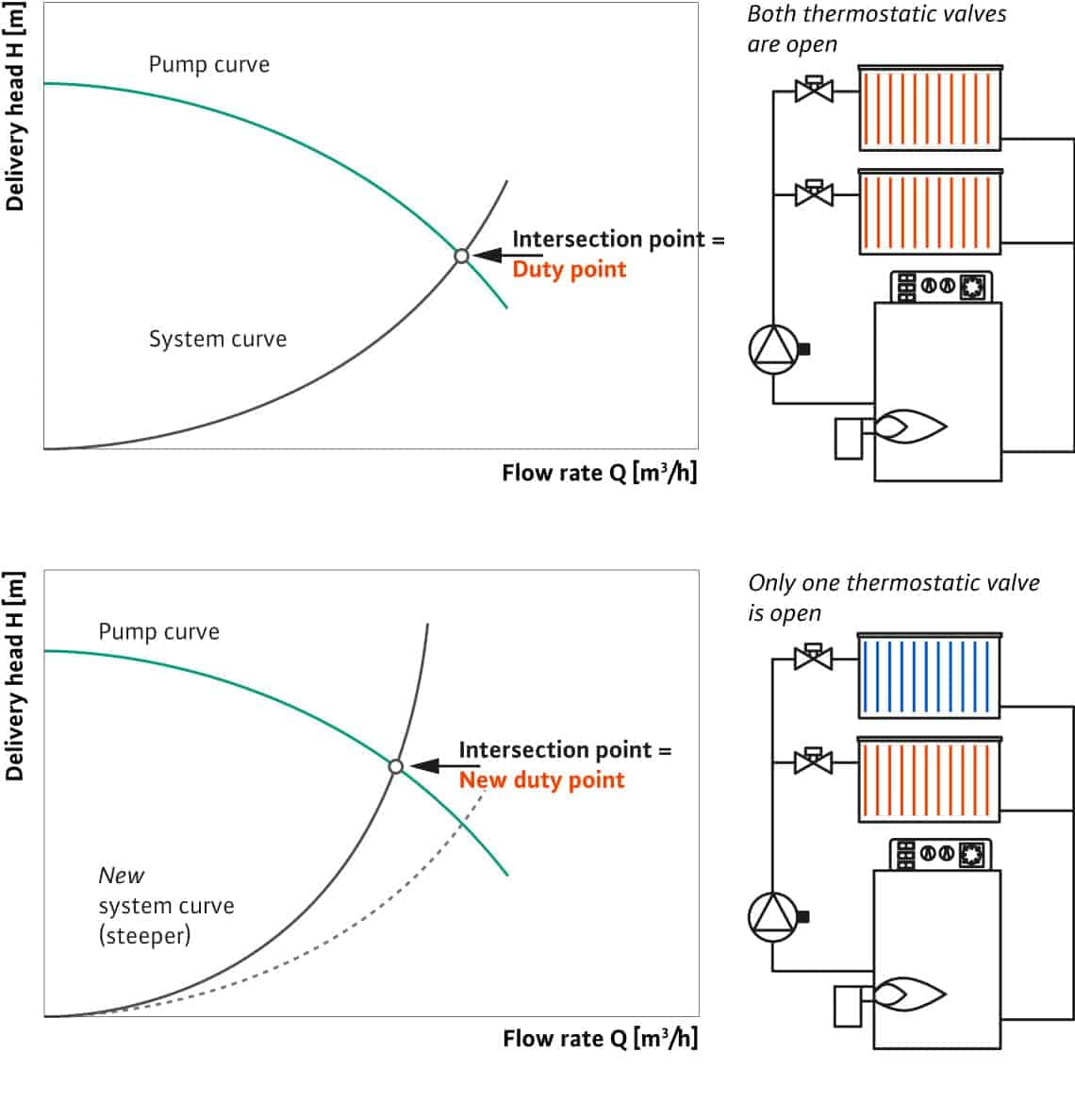
Duty point
The current duty point of the heating or water-supply system is located where the pump and the system curves intersect.
This means, that at that point, there is a balance between the power offered by the pump and the power consumed by the pipe system. The pump’s delivery head is always the same as the flow resistance of the system. This then results in the flow that can be supplied by the pump.
It must be taken into account that the flow rate may not be lower than a certain minimum flow rate. Otherwise, the pump room may overheat and cause the pump to break down. Please observe the manufacturer's information. A duty point outside the pump curve will cause the motor to be damaged.
Due to the change in capacity during operation, the duty point also changes constantly. The consultant must find a design point that is tailored to the maximum requirements. With heating circulators, this is the required heat of the building, with pressure-boosting systems, it is the peak flow for all tapping points.
All other duty points that occur in practical operation, are in the characteristic curve to the left of this design point.
The two figures on the right show that the change in the duty point is caused by the change in the flow resistance.
When the duty point is shifted to the left from the design point, the delivery head of the pump is automatically increased. This creates flow noises in the valves.
The delivery head and flow are adapted to the requirements by installing controlled pumps. At the same time, operating costs are significantly reduced.

Pump selection software helps you find the right centrifugal pump
Selecting the right pump based on important characteristics is almost impossible to do manually. With a pump selection software such as Wilo-Select, you have a complete and effective selection service. You have all the necessary data at your disposal from the calculation to the design of the pump and the accompanying documentation.
Wilo-Select can be used online or installed locally on your computer.
This allows you to edit the following menu items practically:
- calculation;
- design;
- catalogue & article research;
- pump replacement;
- documentation;
- energy cost and depreciation calculations;
- life cycle costs (LCC);
- data export to Acrobat PDF, DXF, GAEB, Datanorm, VDMA, VDI, CEF;
- automatic internet updates.
Professional advice for the right centrifugal pump
We think it is important that you make the right choice, so that you achieve maximum energy efficiency, enjoy maximum comfort, and the pump continues to function reliably.
Every day, Wilo employees make many pump selections for an enormous diversity of applications and systems. As a result, we know what to pay attention to and what data we need to select the right pump for you.