Wilo-SiBoost Smart Helix VE


Your advantages
- Heavy-duty system featuring stainless steel high-pressure multistage centrifugal pump from the Helix VE series with integrated frequency converter with a superproportionally large control range from 25 Hz to a maximum of 60 Hz
- High energy savings due to pressure-loss optimised hydraulics and optimum load adjustment via variable pressure control (p-v) and parallel synchronous speed control
- High reliability through integrated protection functions such as overload protection, dry-running protection and WMS with automatic deactivation as well as control and leakage detection via optional interface to SCADA connection
- Maximum degree of control performance thanks to use of an SCe control device with LCD display, simple navigation and adjustment using rotary knob
- Integration into building automation via standard Modbus RTU
- Suitability for drinking water for all components in contact with the fluid
Recommended services
Design
Highly efficient water supply unit ready for connection (non self-priming). With 2 to 4 vertically arranged Helix VE series stainless steel high-pressure centrifugal pumps in glanded version switched in parallel; every pump is equipped with an integrated air-cooled frequency converter, incl. Smart Controller SCe
Application
- Fully automatic water supply and pressure boosting in residential, commercial and public buildings, hotels, hospitals, department stores and for industrial systems.
- Pumping of drinking water, process water, cooling water, fire water (apart from fire-fighting systems in accordance with DIN 14462 and with the approval of the local fire safety authorities) or other types of industrial water that do not attack the materials either chemically or mechanically and do not contain abrasive or long-fibre constituents.
Equipment/function
- 2-4 pumps per system of the Helix VE 2 to Helix VE 52 series, with IE4-equivalent standard motor and variable auto control with integrated frequency converter for each pump
- Automatic pump control via Smart Controller SCe
- Parts that come in contact with the fluid are corrosion-resistant
- Base frame made of galvanised steel, with height-adjustable vibration absorbers for insulation against structure-borne noise
- Shut-off valve on the suction and pressure sides of each pump
- Non-return valve on the pressure side of each pump
- Diaphragm pressure vessel 8 l, PN16, pressure side
- Pressure sensor, pressure side
- Pressure gauge, pressure side
- Optional low-water cut-out switchgear and pressure gauge, suction side
Typekey
Example: | Wilo-SiBoost-Smart 4Helix VE 1004 |
SiBoost | System for pressure boosting in the commercial area |
Smart | Control device Smart Controller SCe for pumps with frequency converter |
4 | Number of pumps |
Helix VE | Pump series |
10 | Rated volume flow [m3/h] of the single pump |
04 | Number of single-pump stages |
Technical data
- Mains connections:
- 3~400 ±10%, 50 Hz
- 3~380 ±10%, 60 Hz
- Max. fluid temperature +50 °C (+70 °C optional)
- Max. ambient temperature of 40 °C
- Operating pressure 16 bar (25 bar optional)
- Inlet pressure 10 bar
- Nominal connection diameters:
- On the end pressure side R 1½" – DN 200
- On the inlet side R 1½" – DN 200
- Speed range 1500 – 3500 rpm
- Protection class IP54
- Fuse protection on mains side A, AC 3 according to motor power and EVU regulations
Materials
Helix VE 2 to Helix VE 16
- Impellers, guide vanes, stage housing made of stainless steel 1.4307
- Pump housing of stainless steel 1.4301
- Shaft of stainless steel 1.4057
- 1.4404 shaft protection sleeve
- O-Ring gaskets made of EPDM (FKM gasket on request)
- Pipework made of 1.4301 stainless steel
Helix VE 22 to Helix VE 52
- Impellers, guide vanes, stage housing made of stainless steel 1.4307
- Pump housing made of cataphoretically coated EN-GJL 250 grey cast iron
- Shaft of stainless steel 1.4057
- 1.4404 shaft protection sleeve
- O-Ring gaskets made of EPDM (FKM gasket on request)
- Pipework made of 1.4301 stainless steel
Construction
- Base frame: galvanised steel, with height-adjustable vibration absorbers for comprehensive insulation against structure-borne noise as well as integrated lifting devices; other versions on request
- Pipework: Complete pipework made of stainless steel, suitable for the connection of all conventional piping materials; the pipework is dimensioned according to the overall hydraulic performance of the pressure boosting system
- Pumps: 2 to 4 pumps are used from the series Helix VE 2 to Helix VE 52, switched in parallel. The air-cooled frequency converters mounted on the pump motor enable infinitely variable control between 25 Hz and a maximum of 60 Hz for all pumps of this series. All parts that come in contact with the fluid are made of stainless steel for the Helix VE 2 to Helix VE 16 series or of stainless steel/grey cast iron with cataphoretic coating for the Helix VE 22 to Helix VE 52 series; other versions on request. KTW/WRAS/ACS approval for all parts that come in contact with the fluid
- Valves: Each pump is fitted on the suction and pressure side with a standard shut-off device with DVGW approval mark and on the pressure side with a DVGW/KTW-approved non-return valve.
- Diaphragm pressure vessel: 8 l/PN 16 arranged on the discharge side with a diaphragm made of butyl rubber, with DVGW/KTW approval, completely safe in accordance with food safety laws; for testing and inspection purposes, with a shut-off ball cock with drain and throughflow fitting with DVGW/KTW approval in accordance with DIN 4807
- Pressure sensor: 4 to 20 mA, located on the discharge side for controlling the central Comfort Controller SC
- Pressure indication: pressure gauge (ø 63 mm) arranged on the discharge side; additional digital indication of the discharge pressure in the alphanumeric LC display of the Smart Controller SC
- Control device/controller: The system is equipped with a Smart Controller SC as standard
Scope of delivery
- Factory-mounted, ready-for-connection pressure-boosting system checked for functionality and impermeability
- Installation and operating instructions
Options
Other mains connections on request
Accessories
Accessories must be ordered separately as required. The accessories from the Wilo range include the following:
Larger diaphragm pressure vessel
Safety valve
Dry-running protection system:
Float switch
Compensators
Threaded flanges and caps
Commissioning
General preparations and control measures
Check that all on-site wiring has been performed correctly, in particular the earthing, prior to the initial start-up.
Check that the pipes joints are not under stress.
Fill the system and subject it to a visual inspection for leakages.
Open the shut-off devices at the pumps and in the suction and pressure piping.
Open the pump venting screws and fill the pumps slowly with water to allow the air to escape completely.
Commissioning the system
After all the preparations and checks have been made, switch on the main switch and set the control system to automatic mode. The pressure sensor measures the pressure at hand and transmits a corresponding current signal to the control device. If the pressure is less than the set start-up pressure, depending on the parameter settings and the control mode, it first switches on the base-load pump and, as required, the peak-load pump(s) until the consumer pipes
are filled with water and the set pressure has built up.
Decommissioning the system
If the pressure-boosting system has to be taken out of service for maintenance, repairs or other measures, proceed as follows:
Switch off the voltage supply and secure it against being switched on again by unauthorised persons.
Close the shut-off devices upstream and downstream of the system.
Shut off the diaphragm pressure vessel at the throughflow fitting and drain it.
Drain the system completely if necessary.
Consulting guide
Inlet pressure
The maximum inlet pressure (see Technical data) is to be observed for the system configuration. The maximum permissible inlet pressure is calculated from the maximum operating pressure of the system minus the maximum pump delivery head at Q = 0
Pressure reducer
Fluctuating inlet pressure is compensated by the speed control integrated into each single pump as long as the pressure fluctuation is not greater than the difference between the setpoint pressure value and the zero-delivery head of the single pump at minimum speed. If the pressure fluctuation is greater, a pressure reducing valve must be installed upstream of the system.
Volume flow
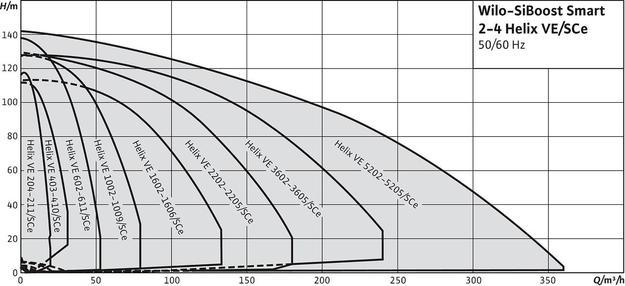
Up to 240 m3/h (66 l/s) system configuration according to DIN 1988 (EN 806); with standby pump up to 320 m3/h (88 l/s) in the event of operation of the pump as an additional peak-load unit
Residual-current devices
When installing residual-current-operated protection switches in conjunction with frequency converters, bear in mind that only universal-current-sensitive residual-current-operated protection switches in accordance with DIN/VDE 0664 are to be fitted.
Wilo-WMS low-water cut-out switchgear
The series Helix VE pump being used is already equipped with an integrated dry-running detection as safety equipment for the pump. The installation of a low-water cut-out switchgear is required if the pressure boosting systems are connected directly to a public mains power supply; this prevents the inlet pressure in the mains supply line from dropping to values below 1.0 bar. Please order directly when ordering the pressure boosting system. The WMS will then be installed in the pressure boosting system by Wilo, electrically wired and fully tested at the final functional test.
Standards/directives
The overall system conforms with the requirements of
- DIN 1988 Part 5
- DIN 1988 Part 6* (**)
* The specifications in DIN 1988 (EN 806) and of the water-supply companies are to be observed. Regarding the electrical components, the system conforms with the requirements of
- VDE 0100 Part 430/Part 540
- VDE 0110 Part 1/Part 2
- VDE 0660 Part 101/Part 107 and
- DIN 40719/IEC 754
Always observe the specifications in DIN 1988 (EN 806) when using and operating the pressure boosting system.(**) That does not apply to fire extinguishing systems in accordance with DIN 14462. Please request these separately.
Installation and operating instructions
Wilo-Helix VE 22-36-52
| Article Number | 4151995 |
| Edition | 1601 |
| Number of pages | 39 |
Wilo-Helix VE 2-4-6-10-6
| Article Number | 4151993 |
| Edition | 1601 |
| Number of pages | 38 |
Wilo-Control SC-Booster (SC, SC-FC, SCe)
| Article Number | 2535460 |
| Edition | 1809 |
| Number of pages | 1795 |
Wilo-SiBoost Smart..., Wilo-SiBoost2.0 Smart...
| Article Number | 2535457 |
| Edition | 2023-09 |
| Number of pages | 64 |
Certification booklet
Wilo-SiBoost Smart ...
| Article Number | 2550649 |
| Edition | 1905 |
| Number of pages | 16 |
Wilo-Control SC-Booster (SC, SC-FC, SCe)
| Article Number | 2550530 |
| Edition | 1811 |
| Number of pages | 8 |
Certificate
AH_ZESTAWY SiBoost Smart FC MVISE EXCEL HELIX VE COE-2 EMHIL
| Number of pages | 1 |