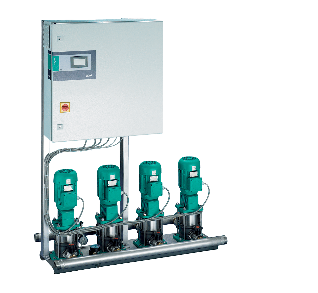
Wilo-Comfort CO-/COR-MVI.../CC


Your advantages
- Easy-to-operate system in accordance with DIN 1988
- 2-6 vertical stainless steel high-pressure centrifugal pumps, switched in parallel, of the MVI series
- Easy-to-use "CC" control device, with memory-programmable microcomputer control and completely graphics-capable touch display, menu-prompted input of operating parameters, available with frequency converter for infinitely variable control of the base-load pump with COR systems
Recommended services
Design
Pressure-boosting system with 2 to 6 parallel-switched, non-self-priming stainless steel high-pressure multistage centrifugal pumps
Application
- Fully automatic water supply and pressure boosting in residential, commercial and public buildings, hotels, hospitals, department stores and industrial systems.
- Pumping of drinking water and process water, cooling water, fire water (apart from fire-fighting systems in accordance with DIN 14462 and with the approval of the local fire safety authorities) or other types of industrial water that do not attack the materials either chemically or mechanically and do not contain abrasive or long-fibre constituents.
Equipment/function
- 2-6 pumps of the MVI series per system
- Automatic pump control via CC Controller
- Components that come in contact with fluid are corrosion-resistant
- Base frame galvanised, with height-adjustable vibration absorbers for insulation against structure-borne noise
- Check valve at each pump, on the suction and pressure sides
- Non-return valve, pressure side
- Diaphragm pressure vessel 8 l, PN16, pressure side
- Pressure sensor, on the discharge side
- Optional pressure gauge, suction side
- Pressure gauge, discharge side
- Optional low-water cut-out switchgear
Typekey
Example: | Wilo-COR-4 MVI 804/CC |
CO | Compact pressure boosting system |
R | Control of the respective base-load pump by frequency converters |
4 | Number of pumps |
MVI | Pump series |
8 | Rated volume flow of the single pump [m3/h] |
04 | Number of single-pump stages |
CC | Control unit; CC = Comfort-Controller |
Technical data
- Mains connection 3~230 V/400 V ± 10%, 50 Hz
- Max. fluid temperature 50 °C (70 °C optional)
- Operating pressure 16 bar (25 bar optional)
- Inlet pressure 10 bar
- Nominal connection diameters on discharge side R 1½ - DN 200
- Nominal connection diameter on the intake side R 1½" - DN 200
- Rated speed 2850 rpm
- Protection class IP 54 (CC control device)
- Fuse protection on mains side AC 3 according to motor power and EVU regulations
- Approved fluids (other fluids on request):Note on fluids: Approved fluids are generally water mixtures which do not chemically or mechanically attack the materials used and do not contain either abrasive or fibrous matter
- Drinking water and domestic hot water
- Cooling water
- Fire water
Materials
MVI 1.. to 16..-6
- Impellers and stage chambers made of 1.4301/1.4404 stainless steel (MVI 16..-6 only in 1.4301)
- Pump housing made of 1.4301/1.4404 stainless steel
- Shaft 1.4301/1.4404 stainless steel
- Gasket EPDM (EP 851) / FKM (Viton)
- Housing cover made of 1.4301/1.4404 stainless steel
- Housing bottom 1.4301/1.4404 stainless steel
- Mechanical seal B-carbon/tungsten carbide, SiC/carbon
- Pressure shroud 1.4301/1.4404 stainless steel
- Bearing, tungsten carbide
- Pump base EN-GJL-250
- Pipework made of 1.4404 stainless steel
MVI 16.. to 95..
- Impellers 1.4301/1.4404 stainless steel
- Stage chambers 1.4301/1.4404 stainless steel
- Pump housing EN-GJL-250/1.4404
- Shaft 1.4057/1.4404 stainless steel
- Gasket EPDM (EP 851) / FKM (Viton)
- Housing cover made of 1.4301/1.4404 stainless steel
- Housing bottom 1.4301/1.4404 stainless steel
- Mechanical seal B-carbon/tungsten carbide, SiC/carbon
- Pressure shroud 1.4301/1.4404 stainless steel
- Bearing, tungsten carbide
- Pipework made of 1.4404 stainless steel
Construction
- Base frame: galvanised and provided with height-adjustable vibration absorbers for comprehensive insulation against structure-borne noise; other versions on request
- Pipework: complete pipework made of stainless steel, suitable for the connection of all piping materials used in building services; the pipework is dimensioned according to the overall hydraulic performance of the pressure boosting system
- Pumps: 2 to 6 pumps of the MVI 2 to MVI 95 series switched in parallel are used; all pump components in contact with fluid are made of stainless or, starting with MVI 16.., of grey cast iron (cataphoretic-coated) or stainless steel on request
- Valves: each pump is fitted on the suction and pressure side with a check valve with DVGW approval mark or annular shut-off valves and a pressure-side DVGW-approved non-return valve
- Diaphragm pressure vessel: 8 l/PN 16 located on the discharge side with a butyl rubber diaphragm, completely safe in accordance with food safety laws, for testing and inspection purposes, with shut-off ball cock, with drain and throughflow fitting according to DIN 4807
- Pressure sensor: 4 to 20 mA, located on the discharge side for activating the central Comfort Controller
- Pressure display: suction- and discharge-side pressure gauge (ø 63 mm); additional digital display of discharge pressure in the alphanumeric touchscreen of the Comfort Controller.
- Switchgear/controller: the system is equipped with a CC Comfort Controller as standard; COR additionally with a frequency converter
Scope of delivery
- Factory-mounted, connection-ready pressure-boosting system checked for functionality and impermeability
- Packaging
- Installation and operating instructions
Options
Series design without casing. Noise-attenuation casing on request.
Consulting guide
Pressure reducer
Fluctuating inlet pressure is compensated by the speed control integrated into each single pump as long as the pressure fluctuation is not greater than the difference between the setpoint pressure value and the zero-delivery head of the single pump at minimum speed. If the pressure fluctuation is greater, a pressure reducing valve must be installed upstream of the system.
Residual-current devices
When installing residual-current-operated protection switches in conjunction with frequency converters, bear in mind that only universal-current-sensitive residual-current-operated protection switches in accordance with DIN/VDE 0664 are to be fitted.
Inlet pressure The maximum inlet pressure (see Technical data) must be taken into account when configuring the system. The maximum inlet pressure is calculated from the maximum system operating pressure minus the maximum pump delivery head at Q = 0.
Only for fire protection systems
Version in accordance with DIN 1988 (EN 806), part 5+6
Always observe the specifications in DIN 1988 (EN 806) when using and operating the pressure boosting system.
Installation and operating instructions
Wilo-MultiVert-MVI 2.. / 4.. / 8.. / 16..-6
| Article Number | 2050778 |
| Edition | 1502 |
| Number of pages | 15 |
Wilo-Multivert MVI 16../32../52../70../95..
| Article Number | 2040502 |
| Edition | 1606 |
| Number of pages | 14 |
Wilo-MultiVert MVI 16../32../52../70../95..
| Article Number | 2040502 |
| Edition | 1606 |
| Number of pages | 17 |
Wilo-Multivert-MVI 2.. / 4.. / 8.. / 16..-6
| Article Number | 2050778 |
| Edition | 1502 |
| Number of pages | 100 |
Wilo-Multivert-MVI 2.. / 4.. / 8.. / 16..-6
| Article Number | 2050778 |
| Edition | 1502 |
| Number of pages | 15 |
Wilo-Comfort CO(R) .. MVI .../ .. MVIS .../ .. Helix V .../.. Helix VE ...
| Article Number | 2535456 |
| Edition | 2021-09 |
| Number of pages | 40 |
Wilo-Control CC-Booster (CC, CC-FC, CCe)
| Article Number | 2552577 |
| Edition | 2020-12 |
| Number of pages | 26 |
Certificate
Atest PZH Zestawy CO, COR
| Number of pages | 1 |
Battery Test Summary UN38.3 CR2450
| Number of pages | 1 |