Powering Fluid Flow: Facts about “Between the Bearings” Pumps
Between the bearings pumps are a type of centrifugal pump designed for high-flow, high-pressure applications across various industries. As the name suggests, these pumps feature an impeller supported by bearings on both sides, giving them stability, balance, and the ability to handle demanding workloads with precision. They are commonly found in municipalities, oil and gas, chemical processing, power generation, and other industrial environments requiring consistent, high-performance fluid handling.

What Are Between the Bearings Pumps?
The unique feature of between-the-bearings pumps is their impeller, which is supported by bearings on both sides rather than just one (Image 1) This dual-bearing configuration helps distribute forces more evenly across the impeller, reducing vibration, minimizing wear on the shaft, and enhancing overall pump stability. These characteristics make between-the-bearings pumps particularly suited for high-flow, high-pressure applications where other pumps might struggle to maintain consistent performance.
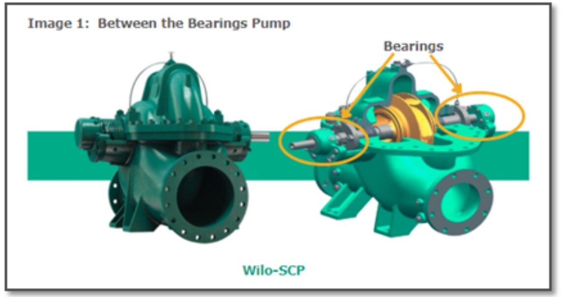
Between the bearing pumps also called “split case” pumps because they have a casing that is "split" into two sections, allowing easy access to the internal components. This design makes maintenance easier as it allows operators to inspect and replace parts without completely disassembling the pump from its piping system.
Key Components and Operating Principle
Key Components and Operating Principle
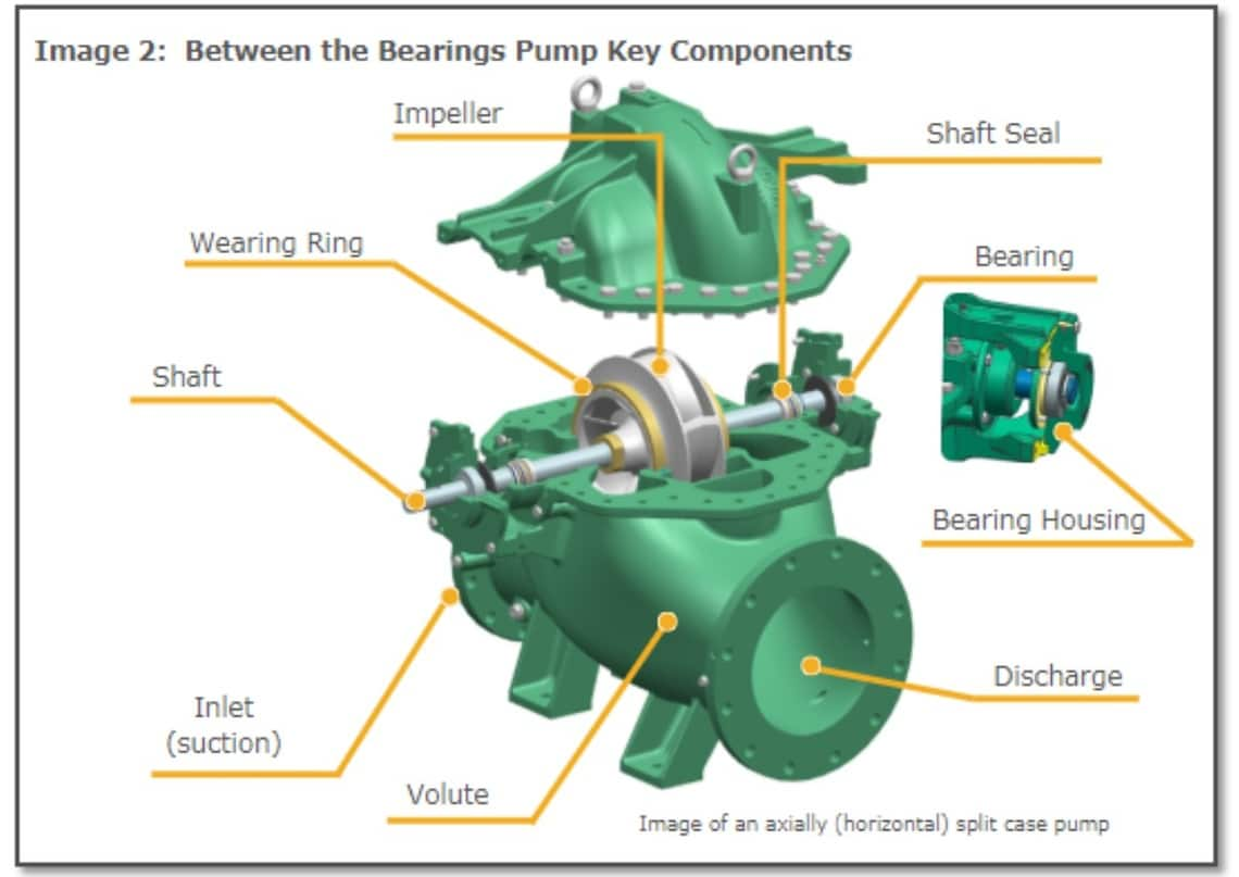
Between the bearings pumps are defined by their robust construction and dual-bearing setup, which supports the impeller on both ends. Here are some key components (Image 2):
- Impeller: The impeller, central to the pump's operation, is placed between bearings on either side, ensuring balance and minimizing axial loads.
- Shaft and Bearings: The shaft, supported by bearings on both ends, provides stability and reduces wear, enhancing pump longevity.
- Volute: The volute (casing) can be designed as either axially split (splits horizontally, parallel to the shaft axis, as illustrated in Image 2) or radially split (vertically, perpendicular to the shaft axis and parallel to the impeller). The choice depends on the pump’s pressure requirements and maintenance considerations.
- Shaft Seals: A shaft seal is a sealing component located on the rotating shaft where it passes through the pump casing. Its primary function is to minimize fluid leakage from the pump and prevent air from entering the casing. Shaft seals range from basic packing glands to more advanced mechanical seals, depending on the application and performance requirements.
- Suction and Discharge Ports: These ports allow fluid to enter and exit the pump at the appropriate pressure and flow rate. The inlet and discharge are on either side of the bottom half of the casing, allowing the top half to be easily removed and provide access to the impeller.
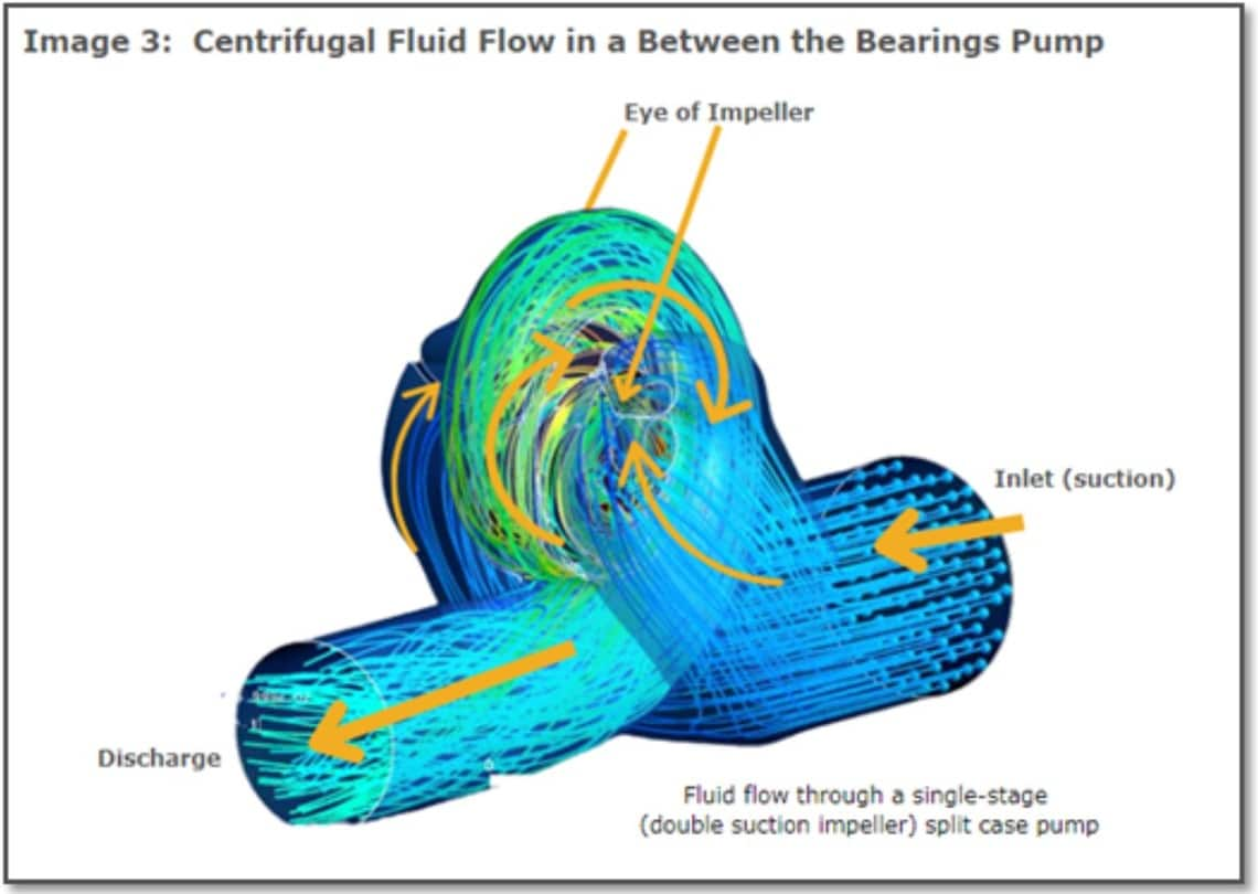
Like all centrifugal pumps, split case pumps operate based on the principles of centrifugal force. In a split case pump, fluid is drawn into the suction inlet and then enters the impeller. As the impeller rotates, it imparts energy to the fluid, causing it to move radially outward, creating a low-pressure area at the eye of the impeller that continuously draws in more fluid. The fluid is then pushed outwards toward the outer edges of the impeller and exits at a higher pressure (Image 3).
Types of Between the Bearings Pumps
Between the bearings pumps are classified within two major categories consisting of the number of stages, and the casing configuration. Wilo produces between-the-bearings pumps that are 1 or 2 stages and are axially split, which will be the focus of this factsheet.
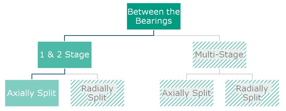
Impeller Design: Single-stage and two-stage pumps are centrifugal pumps distinguished by the number of impellers they use to increase pressure and move fluid (Image 4).
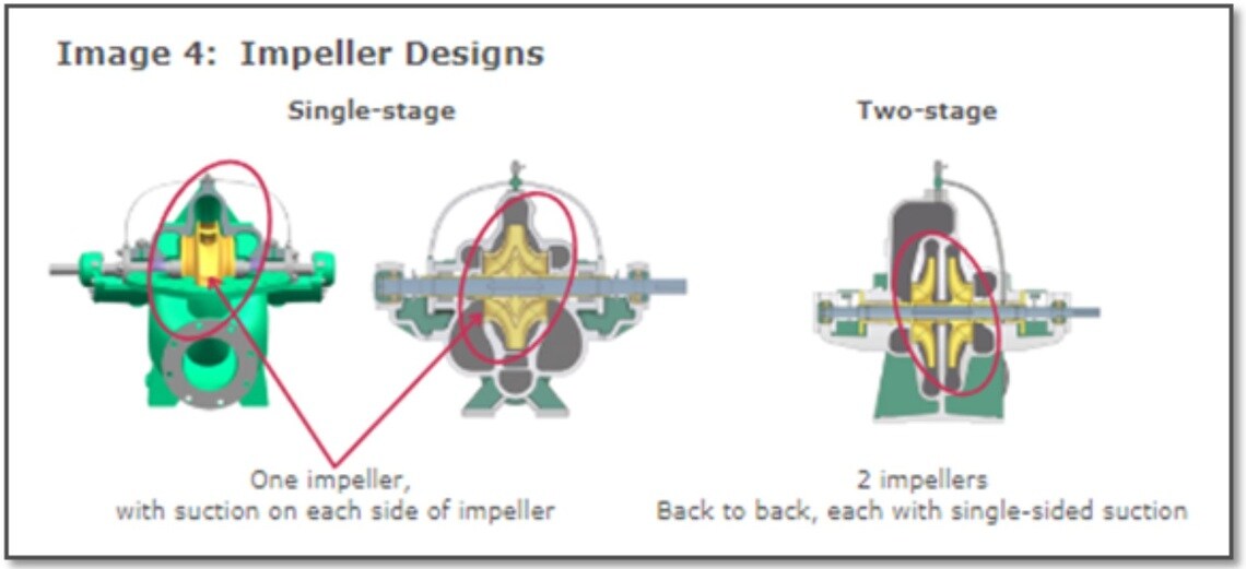
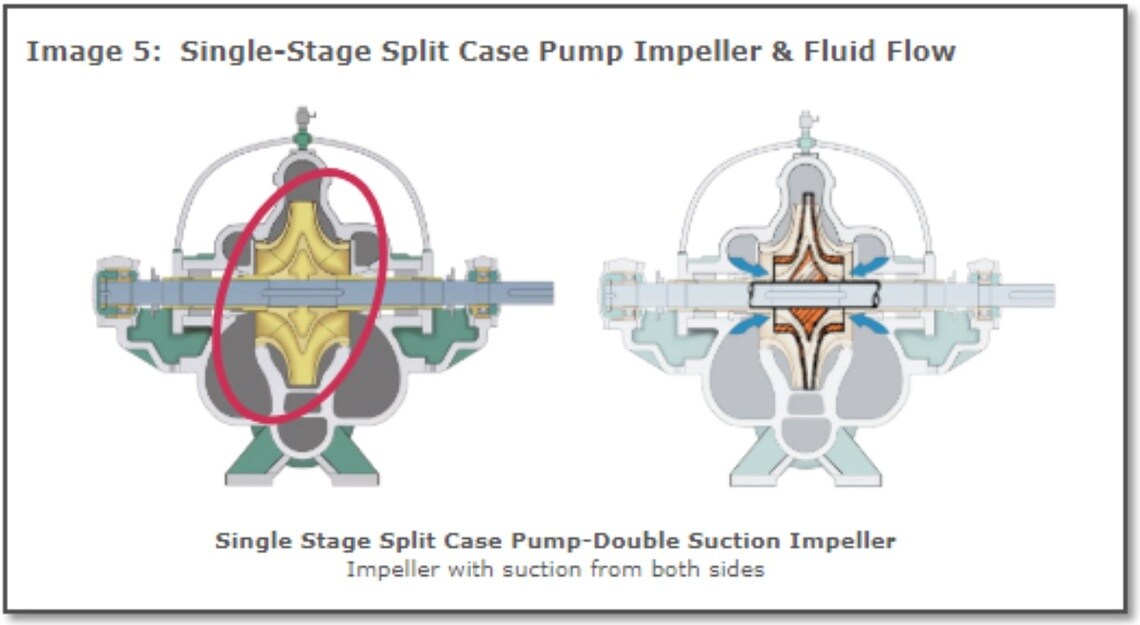
- Single-stage: The single stage, axially split case pump is the most common type (Image 5). It features a single impeller to generate fluid pressure and flow. In this design, fluid is drawn into the pump from both sides of the impeller, a configuration known as a double-suction impeller. This design accelerates the fluid and discharges it at a higher pressure. The double suction acts like two pumps operating in parallel, increasing fluid flow. The double-suction impeller improves balance and reduces axial load on the pump bearings. The double-suction impeller design provides key operational benefits. It lowers the Net Positive Suction Head Required (NPSHR), reducing the pump’s susceptibility to cavitation. Additionally, it minimizes axial thrust and vibration, which stabilizes the impeller on both sides and ensures balanced, efficient operation with less wear over time.
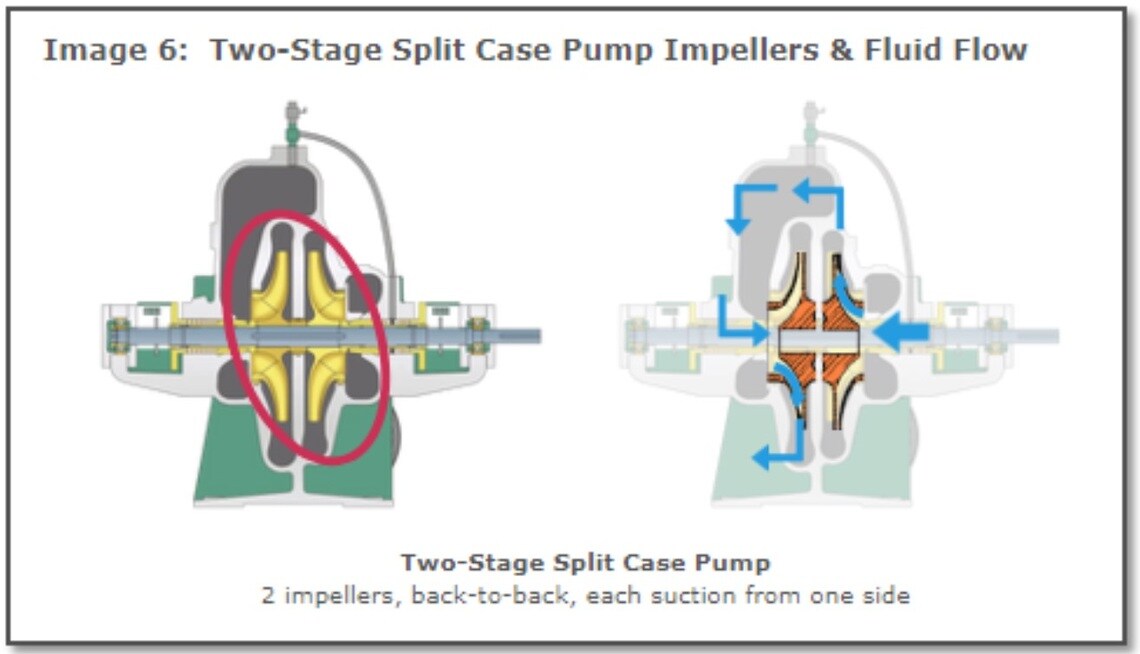
- Two-stage: Two-stage pumps, as the name suggests, have two impellers arranged back-to-back (Image 6). Each impeller is a single-suction impeller, drawing fluid from one side only. A two-stage pump acts like two pumps operating in a series, where the flow remains constant, and the head increases with each stage. The first impeller increases the fluid’s pressure, and the fluid is then directed to the second impeller, which further increases the pressure.
Casing Configuration
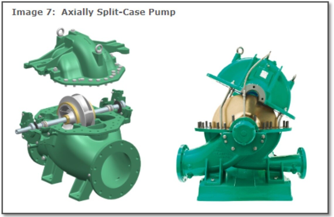
The between the bearings are further classified based on their casing configuration. Split case pumps can be separated axially (Image 7), allowing access to the impeller from above, or they can separate radially, providing access to the impeller from one end of the pump. Most split case pumps are axially split.
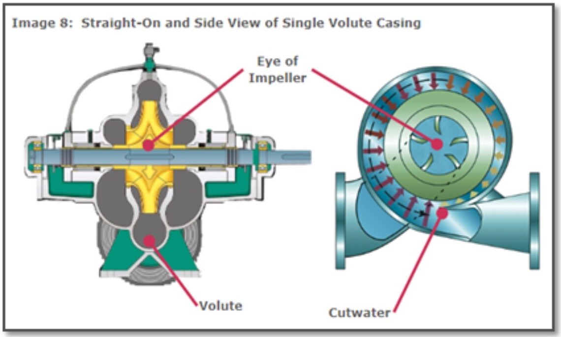
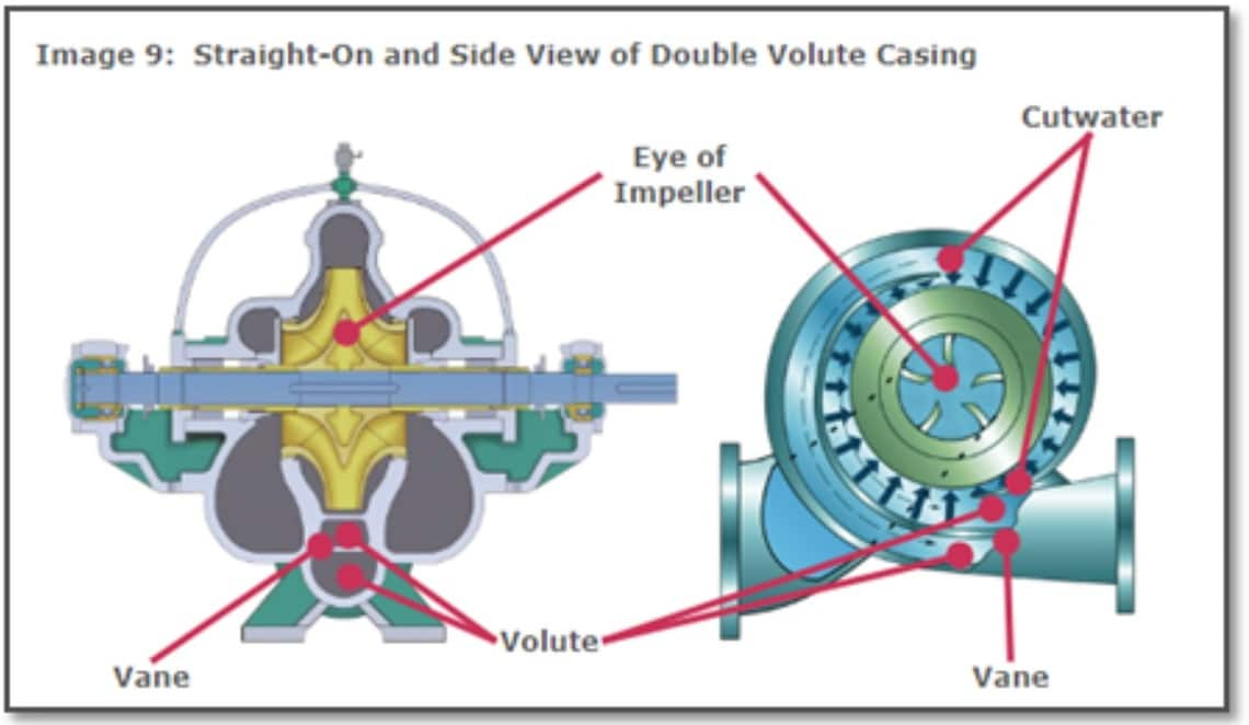
Casings can also be single or double volute design. Single and double volute casings differ in design and application to manage hydraulic forces and performance in centrifugal pumps. The choice between single and double volute casings depends on application requirements, such as flow rates, pressure, efficiency, and maintenance priorities.
Single Volute (Image 8):
- Features a single cutwater guiding fluid from the impeller to the pump discharge.
- Can experience uneven radial forces at higher flows, leading to increased wear and vibration.
- Suitable for low-flow or low-pressure applications.
- Simple in design and cost-effective to manufacture.
Double Volute (Image 9):
- Incorporates two cutwaters located 180 degrees apart from each other, channels symmetrically arranged around the impeller.
- Balance radial forces more effectively, reducing vibration and wear on the pump bearings.
- Ideal for high-flow, high-pressure applications or where long-term durability is essential.
- Slightly more complex and costly to manufacture than single volutes.
Advantages and Disadvantages
Despite their versatility, split case pumps come with both advantages and disadvantages that make them suitable for certain applications but less ideal for others.
Advantages of Split Case Pumps
- High Efficiency: Double-suction impellers balance hydraulic forces, reduce axial thrust, and enhance energy efficiency, making them ideal for high-flow applications.
- Ease of Maintenance: The horizontally split casing allows easy access to internal components without disturbing piping, reducing downtime and maintenance costs.
- Reliability and Durability: Built with robust materials, split case pumps minimize vibration and wear, ensuring long service life and dependable performance.
- Lower Operating Costs: Due to their high efficiency and reduced wear and tear, split case pumps tend to have lower energy and maintenance costs compared to other pumps.
Limitations of Split Case Pumps
While split case pumps have many advantages, there are some limitations to consider:
- Limited Suction Lift: Not suitable for high suction lift applications; best for flooded conditions with minimal lift requirements.
- Space and Installation Requirements: Require significant floor space and a sturdy foundation, increasing installation complexity and costs.
- Initial Cost: Robust materials and design result in higher upfront costs, though efficiency and durability can offset these over time.
- Maintenance Complexity: Although the split case design allows for easy maintenance, Specialized design requires skilled maintenance and precise alignment for optimal performance, adding to operational demands.
Summary
Between the bearings pumps provide a balanced design that handles high-pressure, high-flow applications with ease. With their high efficiency, reliability, and ease of maintenance, they are well-suited for industries with demanding fluid handling needs. Although they require more space and have a higher initial cost, their durability and performance make them cost-effective over time in applications where consistent, high-capacity flow is essential.
Wilo is Your Solutions Provider
Wilo USA headquartered in Cedarburg, WI, is a multi-national pump manufacturer and one of the world’s leading premium suppliers of pumps and pumps systems for building services, water management, and the industrial sector. With innovative solutions, smart products, and individual services, Wilo is your solution provider in making water move using intelligent, efficient, and eco-friendly techniques.
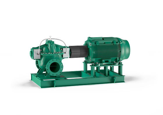
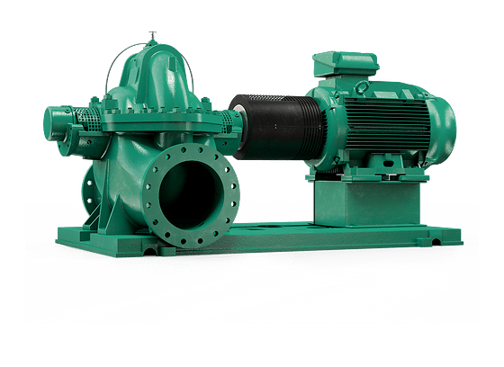
Wilo manufactures a wide range of centrifugal pumps, including “between the bearings” pumps like their single- and 2-stage axially split case models, Wilo-SCP and Wilo-Atmos TERA-SCH-HE. For more information regarding Wilo’s axially split case pumps and other sustainable solutions, visit the Wilo USA website or take a quick look through the Wilo Product Guide for more options.
Featured Products
-
Wilo-Atmos TERA-SCH-HE
-
Wilo-SCP

